Logische E/A
Mit Logical I/O ist es möglich, Aktionen basierend auf den ODER- und UND-Operatoren zu erstellen.
Der I/O-Treiber emuliert einen externen I/O, der mit ihm selbst verbunden ist. Beispiel:
Wenn der Kunde beispielsweise bestätigen möchte, dass ein Ereignis der automatischen Nummernschilderkennung (ANPR) ausgelöst wird, wenn sich ein Auto vor der Kamera befindet, kann die logische I/O verwendet werden, um eine „Regel“ zu erstellen, die nur zu einer Aktion führt wenn VCA ein Auto erkennt UND gleichzeitig ein ANPR-Leseereignis stattfindet.
Ein anderes Beispiel könnte sein, dass ein Eingangs-„Tor“ mit zwei Türen das Öffnen der zweiten Tür nur zulässt, wenn die erste geschlossen ist.
Logische E/A können über dieselbe Schnittstelle wie der Rest der digitalen E/A im System Manager bedient werden.
Eine Lizenz steuert logische E/A und Countdown-E/A. Wenn die Lizenz nicht vorhanden ist, schlägt das Erstellen neuer E/A fehl.
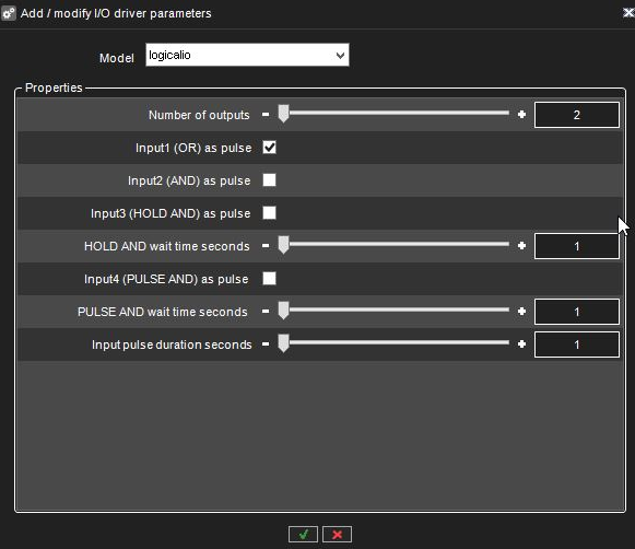
Wenn ein neuer logischer E/A hinzugefügt wird, ist die erste Option im Dialog, wie viele Ausgangszustände als Operanden bei der UND/ODER-Entscheidung verwendet werden.
Die Mindestanzahl beträgt zwei, die Höchstzahl 32.
Alle logischen I/Os generieren automatisch vier Eingänge, die verwendet werden können.
Eingang | Typ |
1 | ODER |
2 | UND |
3 | HALTEN UND |
4 | IMPULS UND |
In den folgenden Abschnitten werden die verschiedenen Eingänge anhand des folgenden Beispiels genauer beschrieben:
Das Beispiel hat 2 Ausgänge, die die Operanden sind. Diese sind in der IO-Liste als Ausgänge 3 und 4 zu sehen.
Die automatisch erstellten 4 Eingänge werden in der Liste als Eingänge 5, 6, 7 und 8 angezeigt.
„ODER“-Eingang
Der erste Eingang, den der logische E/A erzeugt, ist ein ODER-Signal. Wenn einer der Ausgänge eingeschaltet ist, wird der ODER-Eingang eingeschaltet.
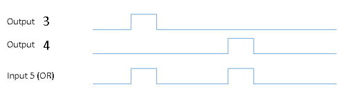
In unserem Beispiel ist Eingang 5 das ODER-Signal. Wenn entweder Ausgang 3 ODER Ausgang 4 eingeschaltet ist, wird als Ergebnis Eingang 5 eingeschaltet.
Der Eingang bleibt so lange eingeschaltet, wie einer der Ausgänge eingeschaltet bleibt. (Es sei denn, der Pulsmodus ist ausgewählt, siehe unten für Details)
„UND“-Eingang
The second input is the AND signal. If all the outputs are on at the same time, the AND input will be turned on. In our example, if both outputs 3 and 4 are on simultaneously, input 6 will be turned on.
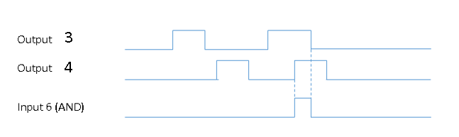
Input will remain on as long as all of the outputs remain on. (Unless pulse mode is selected, see below for details)
“HOLD AND” Input
HOLD AND input become active if all the outputs are active simultaneously, and the time from the first activation to the last activation is less than the time defined in the HOLD AND wait time slider.
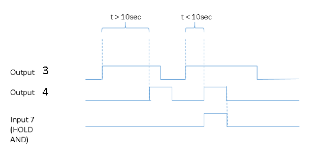
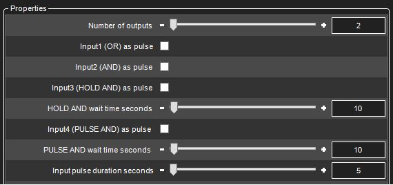
In our example, if output 3 is turned on, and then output 4 is turned on inside 10 seconds, input 7 will become active.
Input will remain on as long as all of the outputs remain on. (Unless pulse mode is selected, see below for details
“PULSE AND” Input
PULSE AND input will become active if all outputs have been active within a specified time.
In our example, if output 3 has been active inside 10 seconds, and output 4 becomes active, then input 8 will be turned on.
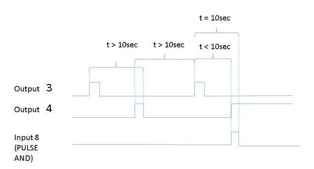
Input 8 remains until the specified time has elapsed from the oldest activating output (unless pulse mode is selected, see below for details).
In our example, when 10 seconds have elapsed from output 3 activation, input 8 will be turned off.
Pulse Mode For Inputs
For each of the four inputs, it is possible to define pulse mode to be in use.
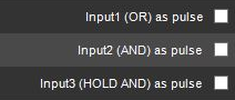
and

The pulse duration can also be adjusted.

If the pulse mode is in use, the input will turn off after the set pulse duration.
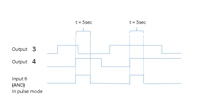
If in our example, we would set the AND input to be in pulse mode like this:

It would mean behaviour like this: