Given requirements apply to all Mirasys VMS installations.
General
Gigabit Ethernet is required on both the client and the server-side.
Data can be transmitted over the Internet, or any other network using TCP/IP.
It is heavily recommended to have two 1 Gb/s network adapters on each server: one for the camera connections and another for server-client and server-server communications.
In the case of large systems with multiple high resolution and high frame rate cameras, separating specific camera sets into their own networks (and adding network adapters to servers) can be recommended.
However, this is done case-by-case and requires case-specific calculations on network load.
Control of PTZ cameras requires the network to have low latency in order to make dome control as responsive as possible.
Example Network configuration:
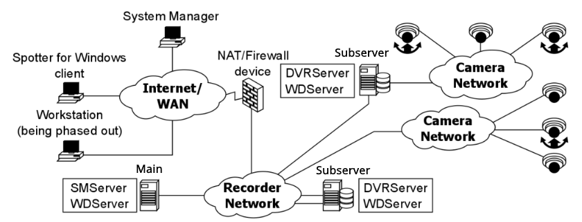
The best practice with the system for security and network performance would be to have the cameras separated from the rest of the network.
This can be done in two ways: having them physically separated or having them logically separated.
Physically separating cameras would involve connecting them to their own local network switch and having the switch connect to a recording server’s network adapter assigned to the camera network.
Example topology of this network principle is presented in the above network.
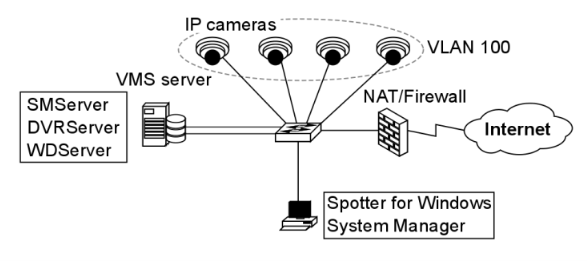
Another method of separating the cameras in the network would be to use VLANs (Virtual LAN) on the switch to logically separate them to their own virtual network.
This manner of networking should be left for smaller operators and isolated surveillance sites with their own ICT workers. VLANs are elaborated in chapter 4.5. An example of this network principle is presented below.
Camera Power
Though it is not strictly a networking issue as far as data transmission is concerned, PoE (Power over Ethernet) devices have to be considered when setting up a network.
Many IP cameras that are set up today for indoor and sheltered outdoor use PoE, meaning they strain a server’s or switch’s power source, with each PoE-enabled port providing up to 30W of power (under 25W normally, up to 30W on PoE Plus).
|
PoE type/Class |
Max power at source |
Max power at camera w/ 100m cable |
Security uses |
|
802.3af (Class 0) |
15.4 |
0.44 - 12.95 |
Indoor/outdoor |
|
802.3af (Class 0) |
4.0 |
0.44 - 3.84 |
Uncommon |
|
802.3af (Class 0) |
7.0 |
3.84 - 6.49 |
Uncommon |
|
802.3af (Class 0) |
15.4 |
6.49 - 12.95 |
Most devices |
|
802.3at (Class 0) PoE+, High PoE |
30.0 |
12.95 - 25.50 |
PTZ cameras, high-power heaters |
|
**All power measurements are in Watts |
|||
A 48 PoE+ port switch at full use and full power draw would be under a total demand of 1440W, though the power output of the device could be much lower.
Connecting too many devices reliant on PoE to a networking device or computer may cause network or system disruptions due to having insufficient power.
Negative consequences of using too many PoE devices at a time on a PoE-providing switch or computer:
-
A blown-out power supply
-
Often produces smoke and is a potential fire hazard
-
If no backup power supplies are installed, the device is disabled
-
-
Reduced power to all devices with degraded service from all the attached devices
-
Additional PoE-using devices cannot be powered
-
Shorter UPS battery life. Normally a UPS can provide around 20 minutes of backup power, but PoE use can shorten this down to 3 minutes.
Keep in mind the power requirements of the cameras, whether they require their own electrical network connection or use PoE.
Some additional hardware on cameras may require their own power source, e.g. dome heater, integrated IR, PTZ, etc. Consult your device documentation when handling PoE solutions.
Network Card Settings
Network card setting requirements:
-
Interrupt Moderation Rate: Extreme
-
Receive Buffers/Receive Descriptors: 2048
-
Transmit Buffers/Transmit Descriptors: 2048
These settings must be according to the requirements, or the network does not function with the system. If the buffers are set to too low, it will cause issues with signaling and video transmissions.
Windows updates could reset network settings to their defaults, so Windows updates need to be monitored and network settings need to be checked with every update.
The necessity of installing Windows updates in a closed network should be evaluated.
In a connected network, all instances of installing Windows updates need to be performed as planned maintenance activities, as software firewall port settings might be reset along with network settings.
Network settings can be changed in Microsoft operating systems through the Device Manager.
The following guide is for modifying Windows network settings, where Interrupt Moderation Rate and Buffer/Descriptors settings are concerned:
-
Open the device manager
-
Open the Start menu
-
Select Control Panel
-
Click Hardware & Sound
-
Click Device Manager
-
-
Open the Network Card settings
-
In the Device Manager, expand Network Adapters
-
Select the computer’s physical network connection
-
Usually marked with “Network Connection” in the label
-
-
Right-click the selected adaptor and click Properties
-
-
Edit the settings
-
Open the Advanced tab
-
Select Interrupt Rate
-
Make sure the drop-down bar has “Enabled” on it
-
-
Select Interrupt Moderation Rate
-
Select “Extreme” on the drop-down bar
-
-
Scroll down and select Receive Buffers (could also be labelled Receive Descriptors)
-
Enter 2048 in the Value bar.
-
-
Scroll down and select Transmit Buffers (could also be labelled Transmit Descriptors)
-
Enter 2048 in the Value bar.
-
-