Mirasys VMS system components are optimized for effective bandwidth usage.
The amount of bandwidth used by the system is determined by the system’s component structure and functional requirements.
In case of network bandwidth problems, the system can automatically prioritize presentation functions and restrict image display rates to avoid network load problems.
The total bandwidth consumption by cameras in the network needs to be noted and taken into account when planning and implementing the VMS network.
As each individual camera consumes bandwidth on its connection, the cameras in the system have a sum of bandwidth that they consume as a whole.
Each connection with multiple cameras should be planned with this in mind.
When the end-user logs into the system by starting the Spotter for Windows or System Manager applications, the invisible background updater application – VAU – connects to SMServer to check for application updates.
If the applications are up to date, the user is successfully logged in and the Main Server will deliver profile information including the IP addresses of the subservers to the client application.
After the end-user has successfully logged into the system, the end-user can view or edit the system settings through the System Manager application, or access information from the analogue and digital devices through the Spotter application.
Local Recording
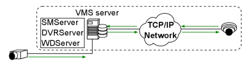
Local recording consists of cameras relaying video signals to recording VMS servers either directly or through the network.
Signals from analogue video cameras and microphones are transmitted through analogue cables to VMS servers physically set up to function as DVRs (Digital Video Recorders) and as such have no bandwidth requirements. As an exception, an analogue camera can be connected to an IP encoder, which would connect to the recorder through the local network.
In these cases, the digital video streams create network traffic only between the encoders and the servers. An encoder gives each analogue camera its own IP address.
The signal from a digital IP based video camera is relayed in a digital format from the camera to the recording VMS servers through the local network.
A recording VMS server is by default an NVR (Network Video Recorder) server. The digital video streams create network traffic only between the IP cameras and the servers.
The bandwidth requirements of a digital data stream from an IP camera depends on the format (typically H.264, H.265 or MJPEG) of the video, as well as the image rate and the resolution of the digital video stream.
Real-time Monitoring
In real-time monitoring, the end-user can view one or multiple videos or audio streams from one or multiple servers.
Each video or audio stream is transmitted from the servers running DVRServer to the Spotter client as a separate stream.
As the client requests each presented image from the DVRServer, the system can automatically adjust the display rate in case the load exceeds the capabilities of the network or of the Spotter client.
The display rate is adjusted by reducing the number of images displayed. However, at least one image per second is displayed.
This adjustment does not affect the recording process, only the real-time monitoring function.
The quality rating, as it is managed through the System Manager application, for each camera is dependent on the camera model.
If the camera model’s API supports video stream quality settings, the System Manager will use the camera’s video quality values as its basis for the VMS video quality value, as measured in percentages.
If a camera does not support quality settings, the quality for video streams in the VMS is based on the bitrate of the video.
The bandwidth requirements of video and audio streams depend on a variety of factors, e.g. the resolution of the streams.
Note that if real-time monitoring is performed directly on a VMS server (e.g. a Spotter for Windows client is installed directly on the server running DVRServer), the video streams do not create any network load.
However, presenting the video streams locally requires additional system resources from the VMS server running DVRServer.
Playback Viewing
In playback viewing, the user can view one or multiple videos or audio streams from one or multiple DVRServers.
Each video or audio stream is transmitted from the recording servers to the Spotter client as a separate stream.
In playback viewing, every recorded picture is displayed.
If the bandwidth usage between DVRServer and the Spotter client exceeds the capabilities of the network, the system will automatically lower the display rates of the streams, resulting in a slightly slower display rate but ensuring that all images are displayed correctly with no gaps in the presentation.
Reverse playback is played at one frame per second.
The bandwidth requirements of video and audio streams depend on the resolution and quality of the streams.
Note that if real-time monitoring is performed directly on a VMS server (e.g. a Spotter for Windows client is installed directly on the recording server), the video streams do not create any network load.
However, presenting the video streams locally requires additional resources from the server.
Alarm Handling
On the occurrence of an alarm, the system prioritizes the alarm procedure, providing maximum possible resources for displaying the alarm view as real-time or playback presentation depending on the system settings.
If additional real-time or playback views are active while an alarm view is displayed, the system will automatically determine the number of resources provided to the additional views based on the needs of the alarm view.
Exporting Media
When exporting segments of the recorded video feed to external media, the system will load the selected clip to the client computer and save the export file to the desired external device (e.g. USB flash drives, CDs/DVDs, or hard drives).
Exporting can also be done with a command-line exporter that is included with the GatewayServer and is also available through Mirasys customer support.
The GatewayServer CLI exporter does not burn video data onto optical disks.
The CLI media export command format is presented below (line broken for better readability). Each argument is preceded by a space and two dashes.
"C:\Program Files (x86)\DVMS\SystemManagement\ Vau\Workstation\MediaExporterCA.exe"
--profile "[profile name]"
--username [username] --password [password]
--devicepaths "[/site/device]"
--startdate [DDMMYYYY] --starttime [hhmmss]
--stopdate [DDMMYYYY] --stoptime [hhmmss]
--file "[destination folder]"
--writer [video file format]
--address [SMServer hostname or IP address]
As exporting video clips from recording VMS servers running DVRServer is completely unrestrained by timing requirements, a video file can be loaded at a rate that will not place an undue burden on the network.
System Manager
The system administrator can view and edit system settings through the System Manager application.
Through the application, the administrator can add and remove recording servers as well as individual devices such as cameras and microphones from the system.
In addition, the administrator can define and edit functions affecting bandwidth requirements such as the video quality of specific cameras.
For example, the administrator can temporarily lower or raise the quality of video recorded from a camera, and the change will directly affect the network load created in video playback or real-time presentation from the specific camera.
Customer Bandwidth Usage
For bandwidth estimation usually below questions should be addressed:
-
How much bandwidth does each camera use
-
How many simultaneous users are connected to the Mirasys VMS?
-
How many simultaneous video and audio streams will users access?
-
What is the minimum acceptable video resolution and quality required by users?
-
What is the maximum amount of bandwidth required by users?
TIP: Calculate this by multiplying the number of users by the maximum number of streams consumed simultaneously
Bandwidth Usage Examples
|
Resolution |
FPS |
Bandwidth, MJPEG |
Bandwidth, H.264 |
|
2CIF (NTSC) |
5 |
0.64 |
- |
|
2CIF (PAL) |
5 |
0.80 |
- |
|
4CIF (NTSC) |
10 |
2.60 |
- |
|
4CIF (PAL) |
10 |
3.20 |
- |
|
1 megapixel |
5 |
c. 6.70 |
c. 2.15 |
|
2 megapixel |
5 |
c. 8.30 |
c. 2.24 |
|
3 megapixel |
5 |
c. 13.80 |
c. 3.60 |
|
5 megapixel |
5 |
c. 17.20 |
c. 5.20 |
|
**All bandwidth values are in Mb/s **Values are averages based on usage. The bandwidth usage can be heavily affected by the amount of movement in the image, camera settings and focus, and environmental circumstances. |
|||
For comparison, an audio stream for a single microphone would require between 8-50 kb/s on playback and 350 kb/s real-time.
Balancing Video Performance vs Bandwidth And Capacity
In the field of video surveillance, bandwidth is one of the most important practical considerations.
Bandwidth is determined by a number of factors pertaining to the video feed, not just frame rate and video resolution.
An important consideration that often goes overlooked is the concept of scene complexity, where different or changing scenes may require many times more bandwidth, even if viewed through the same camera.
Scene complexity denotes activities and details contained within the viewed scene, but this factor is not a straightforward thing to evaluate.
Understanding bandwidth is critical because it impacts network load and storage use, both of which incur their own costs.
These can be kept down by influencing the recorded scene’s complexity by keeping the factors of it in check.
An important consideration beyond the physical attributes of setting up an image is that the more an image is processed or compressed on one end of video transmission, the more CPU resources are consumed on the other end to “unpack” the video and make it presentable.
So while this chapter focuses on balancing video performance and quality with bandwidth there is a third dimension of computer performance in the background.
It is recommended to test and measure different camera models to find an acceptable balance between performance and bandwidth consumption before any wide-scale deployment.
All performance properties have their own impacts on bandwidth.
A quick way of estimating basic video bandwidth is to calculate a figure based on single frame file size and the frame rate.
|
Megapixel count |
Resolution |
FPS |
Bandwidth |
|
1 |
1280 × 720 |
7 |
0.9 - 1.8 |
|
15 |
1.6 - 3.1 |
||
|
30 |
3.1 - 6.2 |
||
|
1.3 |
1280 × 960 |
7 |
1.2 - 2.4 |
|
15 |
2.1 - 4.1 |
||
|
30 |
4.1 - 8.2 |
||
|
2.0 |
1920 × 1080 |
7 |
1.5 - 3.0 |
|
15 |
2.6 - 5.2 |
||
|
30 |
5.2 - 10.3 |
||
|
3.0 |
2048 × 1536 |
7 |
2.4 - 4.4 |
|
15 |
4.1 - 7.7 |
||
|
30 |
8.2 - 15.4 |
||
|
5.0 |
2560 × 1920 |
7 |
3.5 - 5.7 |
|
15 |
6.1 - 10.1 |
||
|
30 |
12.1 - 16.4 |
||
|
**All bandwidth values are in Mb/s **All resolutions use progressive scanning |
|||
File size for a single uncompressed frame can be calculated from the image properties of the video following the below equations:
Interlaced Factor equals 1 for progressive scan video and 0.5 for interlaced video.
So a quick ballpark for video bandwidth for each camera without taking any other factors, such as compression, into account would be:
Resolution
|
Format |
NTSC-Based |
PAL-Based |
|
QCIF |
176 × 120 |
176 × 144 |
|
CIF |
352 × 240 |
352 × 288 |
|
2CIF |
704 × 240 |
704 × 288 |
|
4CIF |
704 × 480 |
704 × 576 |
|
D1 |
720 × 480 |
720 × 576 |
|
Size/ Format |
Pixels |
|
QQVGA |
160 × 120 |
|
QVGA |
320 × 240 |
|
VGA |
640 × 480 |
|
HDTV |
1280 × 720 |
|
1M |
1280 × 960 |
|
1M |
1280 × 1024 |
|
2M |
1600 × 1200 |
|
HDTV |
1920 × 1080 |
|
3M |
2048 × 1536 |
|
5M |
2560 × 1920 |
|
4K |
4096 × 2160 |
On average, a linear relationship exists between pixel count and bandwidth.
However, variations across manufacturers and models are significant. Some cameras increase at a far less than linear level while others rise at far greater than linear.
There are no obvious factors that distinguished why some models differ in their rate of increase.
So while resolution might be a reasonable ballpark indicator of bandwidth (as indicated in the equation in chapter 5.9), it’s recommended to test and measure each camera model separately.
Some camera models reduce resolution-based bandwidth by cropping an image when lowering the resolution.
Frame Rate
Frame rate impacts bandwidth, but for inter-frame CODECs such as H.264, the potential increase is less than linear.
An increase in frame rate by a factor of 10 would likely lead to a smaller than expected increase in bandwidth, often by a factor of only 3 to 5. This is illustrated in the below table.
|
Video frame rate impact on bandwidth |
|||
|
FPS |
Bandwidth |
FPS increase |
Bandwidth increase |
|
1 |
0.18 |
- |
- |
|
10 |
0.69 |
1000% |
400% |
|
30 |
1.30 |
3000% |
700% |
|
**All bandwidth measurements are in Mb/s **Measurements were done at 1 frame per second with compression Q =28 |
|||
The context of a scene can be used to gauge the normal needed frame rate for regular live footage.
The industry has certain standards and recommended frame rates for normal contexts, listed in the table below.
|
Context |
FPS |
|
Nevada Gaming Commission standard |
30 |
|
Cash register, teller stations |
12-15 |
|
School or office hallways |
4 |
|
Parking lot, traffic and overview cameras |
1-3 |
|
Sports stadiums on non-event days |
<1 |
As image quality and frame rate increase, so do bandwidth requirements.
The frame rate selected should meet business requirements, but it does not need to be higher than what is required and should be considered carefully as frame rate influences both bandwidth and storage requirements.
Motion pictures are captured at 24FPS. Human visual capabilities normally register images captured at 24FPS as fluid motion.
Regular television sets use 25FPS (PAL) or 30FPS (NTSC) as do analogue video cameras.
These rates are often excessive for some video surveillance applications and in most applications less than 12-15 FPS is normally sufficient.
Colour
Colour can be thought of as a third dimension for a frame’s size. Each pixel has a certain pixel depth that determines its colour. At most, 32 bits can be used for a pixel’s colour code.
|
Bit Depth (Bits Per Pixel) |
Number of Colors |
Binary expression |
|
1 |
2 |
21 |
|
2 |
4 |
22 |
|
3 |
8 |
23 |
|
4 |
16 |
24 |
|
6 |
64 |
26 |
|
8 |
256 |
28 |
|
16 |
65 536 |
216 |
|
24 |
16 777 216 |
224 |
|
32 |
4 294 967 296 |
232 |
In practice, colour generally has little impact on compressed video bandwidth, but saturation is an important aspect.
Oversaturated colours increase image complexity through more pronounced colours and colour bleeding.
Gain increases can compound this bandwidth inflation. Desaturation gives small decreases in bandwidth, generally under 10%.
Compression
Compression (or quantization), has an inverse relationship to bandwidth: the more compressed a video or image is, the lower bandwidth will be.
Compression refers to the compression of pixels in a video or image file.
The uncompressed video would require excessively high bandwidth for videos.
In an example situation where the video is uncompressed, a resolution 1080p, full-colour video, with each frame being an I-frame (further elaborated in 5.8.6), streaming at 30FPS would give the following bandwidth calculation:
Compression ratio is the factor over which the original image file size is larger than the compressed file size.
Video or images with a ratio approaching 200:1 are on the higher end of achievable compression with some codecs, and any further compression with lossy formats will lead to significant quality degradation.
Quantization (Q) is a form of compressing images in pixel blocks, where the values of pixels in blocks are arranged as mathematical matrixes, such as 8x8 for MPEG.
Quantization is measured on a 0-51 scale with H.264, though manufacturers often use their own scales. 23 is seen as an average value and a balanced tradeoff between quality and bandwidth.
The higher the number, the higher the compression and the resources digital devices need to invest in encoding and decoding them, conversely, compression leads to quality loss. 0 means a completely lossless (uncompressed) image.
Changing H.264 quantization from high (34) to average (28) results in at least a three-fold bandwidth increase, while further lowering compression to very low (22) results in a 5-to-11-fold increase in bandwidth, depending on the model of the camera.
|
Approximate impact of compression on bandwidth increase |
|||
|
Camera Model |
Q = 34 |
Q = 28 |
Q = 22 |
|
Dahua IPC-HF-3101N |
1 |
x3 |
x5 |
|
Hikvision DS-2CD864FWD-E |
1 |
x3 |
x10 |
|
Samsung SNB-6004 |
1 |
x3 |
x6 |
|
Sony SNC-VB630 |
1 |
x3 |
x11 |
|
**Bandwidth measurements based on Mb/s |
|||
|
**Scene complexity measured in an office environment. Scene complexity and camera settings will affect bandwidth. |
|||
Codec
Codecs can be differentiated by their support of inter-frames or using intra-frames only.
Inter-frame-supporting codecs (e.g. H.264) compress similar pixels in a frame, reference preceding frames and transmit only the pixels changed between frames.
Intra-frame codecs compress each frame and transmit them. Sending only the changed information instead of each frame of video saves the stream significant bandwidth.
Currently manufactured cameras typically use H.264 for its bandwidth-saving advantages over MJPEG and MPEG-4. The advantage is clearly seen in the below chart.
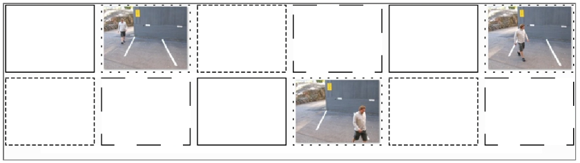
Intra- and Inter-Frames
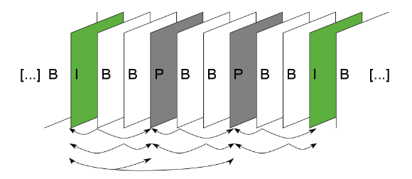
In inter-frame codecs, frames that capture the full field of view are referred to as I-frames, while those sending only changes are P-frames.
Because I-frames capture a full image bandwidth is correlated with the number of I-frames in a stream.
In almost all cases, one I-frame per second is the best balance between bandwidth and image quality.
Too few I-frames in a video stream may negatively impact imaging, with long "trails" of encoding artefacts, while more than one I-frame per second provides little visible benefit.
B-frames are frames that are placed between P-frames and I-frames. B-frames reference both types of preceding and successive frames to form a predictive movement frame. B-frames are usually optional since they increase encoding artefacts in the video.
Reducing the number of I-frames (moving from 1 to 2 to 4-second intervals) produces minimal bandwidth reductions, despite the severe negative image quality impact, as seen in the below chart.
Increasing the number of I-frames to more than one per second can conversely increase bandwidth, as seen in the below chart.
Each set of an I-frame, P-frames referencing it and B-frames referencing (if in use) any of the previous forms a GOP (Group of Pictures/audio).
The recording servers in the VMS save each GOP on separate disks, should a server running DVRServer have multiple hard drives installed, connected or assigned to it.
This method, called SDD (Secure Data Distribution), ensures that always at least a portion of saved video footage is preserved should disk failures occur. In a four-disk SDD setup, drives C:, E:, F: and G: each store a GOP in sequence
Should drives C: and F: fail, E: and G: will still have enough frames to store a serviceable security recording.
If even G: fails, the system can present a serviceable security recording at ~25% of the original recording’s frame rate.
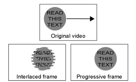
Scan Type
Resolutions are sometimes suffixed with a letter (p or i). This signifies the scan type of the video:
-
Progressive scan video captures and transmits an entire frame at once, meaning the reported frame rate for resolutions marked with p mean full frames per second
-
Interlaced scan video captures and transmits alternating lines for every frame scanned.
-
The individual frames take up less space, but the video has a higher perceived frame rate.
-
A common issue with the interlaced video is a noticeable alignment difference between the scan fields when looking at moving objects. Video resolutions marked with I are interlaced.
-
The interlaced video takes half the bandwidth of progressively scanned video when frame rates and resolutions are shown.
In the field of video surveillance, progressively scanned images are more useful, as single frames can be as important as a whole video clip.
With a moving image, there is a difference in position with the fields of an interlaced scan frame. This can obscure details and make the edges of moving objects fuzzy.
Interlaced video is today largely a hold-over from the days of using CRT (Cathode Ray Tube) monitors, where interlaced scan fields were an easier way to project video with the technology.
Computer monitors display progressive images, so the tearing and artefacts inherent in the interlaced video become more pronounced when viewed through a screen.
Scan type has become less of an issue with the transition to IP cameras. Most IP cameras use progressive frame scanning, while interlaced scanning is more common with analogue cameras.
Gain Control
Gain control is a critical factor in low light surveillance video. It is generally only noticed when the negative side effects of aggressive gain levels are seen, namely noise on the video.
To maintain good video quality, gaining control is necessary.
Bandwidth penalty for increased gain becomes increasingly steep as gain levels increase.
There are some camera models with very high noise and very high bandwidth consumption in low light.
In situations like these, it’s recommended to check one’s low light bandwidth consumption. If it is high, the presence of a bandwidth cap should be verified and lowered if necessary.
The other option is to use CBR streaming or VBR with a cap of maximum bandwidth.
The image below shows our test results of taking a scene with maximum gain and limiting its bandwidth to 1 Mb/s. The overall image quality is practically unchanged but at a fraction of the bandwidth.
Lighting Levels
Camera environments where there are varying light levels present their own challenges to cameras.
Camera manufacturers usually indicate in their product documentation what lighting levels their devices can function in.
Lighting levels are measured in Lux (lx), the SI unit measuring luminance over an area.
The lower the Lux rating on the camera, the better it can see in low light conditions.
|
Approximate lx |
Condition |
|
<0.001 |
Starlight – Overcast night |
|
0.001 – 0.01 |
Starlight – Clear night |
|
0.01 – 0.1 |
Overcast night |
|
0.1 – 1 |
Moonlight at full moon |
|
1 – 100 |
Dusk/twilight, office hallway lighting |
|
100 |
Dark overcast day |
|
320 – 500 |
Office |
|
500 – 1 000 |
Overcast day, TV studio |
|
10 000 – 25 000 |
Bright daylight |
|
32 000 – 100 000 |
Direct sunlight |
Low light environments make cameras suffer from increased digital noise caused by high gain levels.
This noise increase bandwidth by a significant degree. A selection of cameras seen in [Table 12] shows a five-fold increase in average bandwidth during night-time when compared to daytime footage.
|
Camera |
Resolution |
FPS |
Day |
Night |
Relative increase |
|
Arecont AV3116DNv1 |
3MP |
10 |
1.25 |
3.04 |
144% |
|
Avigilon H3 1MP |
720p |
10 |
0.48 |
2.02 |
322% |
|
Axis Q1615 |
1080p |
10 |
0.42 |
4.28 |
909% |
|
Bosch NBN-932V |
1080p |
10 |
0.64 |
3.12 |
388% |
|
Bosch 733 |
720p |
10 |
0.18 |
0.30 |
73% |
|
Dahua HF3100N |
720p |
10 |
0.19 |
3.81 |
1983% |
|
Hikvision 864 |
720p |
10 |
0.56 |
4.72 |
843% |
|
Samsung 5004 |
720p |
10 |
0.68 |
1.86 |
274% |
|
Samsung SNB-6004 |
1080p |
10 |
1.89 |
2.58 |
37% |
|
Sony SNC-VB630 |
1080p |
10 |
2.49 |
8.24 |
231% |
|
Sony VB600B |
720p |
10 |
0.16 |
0.60 |
275% |
|
Averages |
- |
10 |
0.81 |
3.27 |
498% |
|
**All bandwidth measurements are in Mb/s |
|||||
Digital noise can be reduced primarily with two methods: Digital noise reduction and integrated IR.
Noise reduction decreases bandwidth and space requirements by compensating for and smoothing out digital noise in the footage.
Integrated infrared systems function as low-level night vision, improving footage lighting levels and giving a smaller relative increase in bandwidth as seen in the below table.
|
Camera |
Resolution |
FPS |
Day |
Night |
Relative Increase |
|
Axis M1144-L |
720p |
10 |
1.20 |
5.44 |
353% |
|
Avigilon 3.0W-H3A-BO1 |
1080p |
10 |
1.15 |
1.32 |
15% |
|
Dahua HFW3200S |
1080p |
10 |
3.20 |
8.80 |
175% |
|
Hikvision DS-2CD2032-I |
1080p |
10 |
2.75 |
7.20 |
162% |
|
Averages |
- |
10 |
2.08 |
5.69 |
176% |
|
**All bandwidth measurements are in Mb/s |
|||||
When comparing the bandwidth increases of the 1080p resolution cameras in the previous two tables, we see a similar increase in bandwidth (about 3,2Mb/s) when transitioning from day to night, but the relative increase in bandwidth is considerably less when noise reduction methods such as integrated IR are used.
Field Of View
The camera field of view impacts video bandwidth with two factors: the amount of moving elements and scene detail.
Normally when a camera records a larger field of view, it might pick up more moving elements from a background, e.g. view of a street corner might pick up vegetation or signs around the street corner, traffic on or near the corner and nearby pedestrian traffic. Tightening the field of view usually screens out unnecessary areas from the recorded video.
If a camera is zoomed in on a relatively uniform and repetitive scene with relatively little movement, it will pick up finer static details and encoding the video will be more difficult.
Aspect ratio
Another way of restricting a camera’s field of view is by adjusting the camera’s aspect ratio.
With aspect ratios, the camera can be set to record only a segment of its total field of view, scanning the desired section of the scene and leaving out the wasted areas.
CCTV cameras use a 4:3 aspect ratio. Most IP cameras have a default aspect ratio of either 4:3 or 16:9, but high-definition cameras can have their video’s aspect ratio adjusted.
Some cameras support this function natively. Consult device documentation to see if the model used supports this function.
Camera placement
A camera with an overview scene monitors a large area such as a parking lot or a traffic camera that is viewing vehicle congestion or the number of cars parked in the said parking lot.
Because fine details are not important for overview cameras, standard definition resolution used with a wide-angle lens may be sufficient for the task.
Overview cameras may be supplemented with a detail view camera focused on key areas of interest or PTZ cameras to provide real-time analysis of areas of interest at a higher resolution.
Detail view placement means having a camera observing a specific area of interest at a higher resolution than an overview camera.
The detailed view is used for point-of-sale transactions and face or license plate recognition.
A camera assigned for a detail view position may have PTZ capability, be close to the monitored area or have a long focal length lens.
Megapixel or HD cameras may be deployed to provide a sufficient number of pixels-per-area to accurately represent subjects within the field of view.
Sharpness
Sharpening an image increases detail and fidelity by bringing more definition to fine pattern details and object edges.
The tradeoff is that this significantly increases video bandwidth. Conversely, decreasing image sharpness blurs details and edges, but decreases bandwidth.
|
Camera Model |
Minimum |
Default |
Maximum |
|
Axis Q1604 |
0.44 |
0.62 |
1.72 |
|
Dahua HF3101N |
0.69 |
1.64 |
4.83 |
|
Sony VB600 |
0.78 |
0.59 |
1.09 |
|
Average |
0.64 |
0.95 |
2.55 |
|
**All bitrate measurements are in Mb/s |
|||
WDR
WDR (Wide Dynamic Range) is used to balance out varying lighting levels by High-Dynamic-Range Imaging.
This allows a camera to maintain detailed video even with backlight and other harsh lighting conditions.
WDR allows for increased details compared to video-recorded without WDR and possibly more uniform colours in some scenes, making compression easier.
Camera Driver Solutions
Choosing between VBR (Variable BitRate) vs. CBR (Constant BitRate) has an impact on bandwidth, and is significantly determined by what the camera “sees.”
Systems are by default set to CBR. VBR support depends on the capture driver.
With CBR, the camera streams its footage at a constant frame rate without regard to what’s actually happening on the screen.
VBR enables a higher frame rate in the event of alarm activation. Using VBR saves on storage space and average bandwidth, though the bandwidth will fluctuate.
It is recommended to test to find out which solution works better in the camera’s environment.
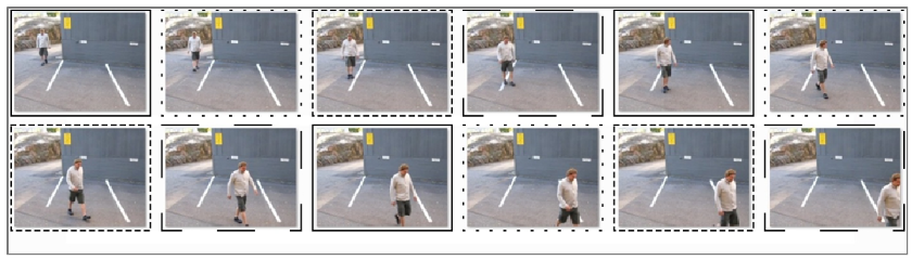
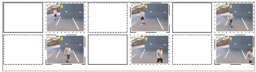
Motion Detection
If camera-based motion detection (VMD, Video Motion Detection) is used to trigger an alarm, nothing is sent/streamed (or recorded) unless the camera detects motion and starts to transmit, or if the client application user decides to view the live camera view.
Normally motion detection is handled by the system server-side. DVRServer uses software VCA for motion detection. This is configured through the System Manager application.
In the System Manager application settings, each camera has a default motion detection mask.
The mask cannot be edited through the application, so it detects motion in the entirety of the image area when it is used.
In addition to the default mask, four more masks can be configured for each camera.
The use of these masks can be scheduled in the application.
A mask contains these parameters:
-
Selected areas. The system detects motion in areas that are painted red.
-
Detection sensitivity.
-
Minimum quantity of movement.
Motion detection methods
Three motion detection algorithms are available:
-
Comparative motion detection compares an image to the image before it. If the differences exceed set limits, the system interprets it as detected motion.
-
Comparative motion detection can be used in most conditions.
-
However, if there is a lot of movement in the background, e.g. rain, moving leaves, or changes in light levels, the use of adaptive motion detection instead is recommended.
-
-
Adaptive motion detection, which compares each image to a learned background image. The system learns the background image and the movement that belongs there automatically.
-
Thus, the system does not interpret constant and predictable movements inherent to the scene as motion.
-
Additionally if more than half of the pixels in an image change, the system concludes that the lighting conditions have changed. As a result, it resets the reference image and starts learning it again.
-
Do note that learning the background image can take some time for the system.
-
-
Hermeneutic motion detection, a sophisticated motion detection system for challenging conditions with “noisy” backgrounds (heavy rain, wind tossing tree branches, etc.) and situations in which external VCA (Video Content Analytics) tools are used. It should be noted that hermeneutic detection requires more processing resources from the server than the other detection methods
Mirasys supports a number of cameras with native VMD. Please consult the list of supported models.
For more information on configuring motion detection for cameras through the VMS, please consult the Mirasys VMS 7.3 Administrator Guide.
Streaming Options
Choice of depending only on a single stream or multiple streams for different purposes also has an impact (when the camera is sending two or three streams simultaneously, vs. only one) on bandwidth.
Using unicast vs multicast has different levels of network impact.
This impact is principally seen with routing, but also in cases where two separate DVRServers can capture the same stream simultaneously.
Multicasting support depends on the camera drivers. Please consult the list of supported camera models.
Network Planning Impact On Bandwidth
To size a video surveillance network, you will need to know:
-
How much bandwidth each camera consumes, depending on the models you have or plan to have
-
How many cameras do you plan to use and in how many locations
-
The distance (administrative or physical) of the DVRServer to the cameras connected to it, presuming they need an IP network
-
What the bandwidth of those network connections is and what pre-existing load those networks must also support
-
What cameras must be viewed live and where/how many viewing stations are in the system
-
How many servers will there be in the network
Video surveillance consumes network bandwidth in two general routes, in some cases at the same time on some networking devices:
-
IP camera/encoder to server: Video is generally produced in devices different than what they are recorded on (e.g., a camera generates video; a VMS server running DVRServer records it).
-
The video needs to be transmitted between the end devices. If it goes over an IP network (e.g., IP cameras to a VMS server running DVRServer), bandwidth is required.
-
-
Server to the client: Statistically, a very low percentage of video is watched by humans. Often, a user is viewing the footage on a device that is connected to a different IP network than the server.
-
For example, the server might be in a rack in a server cabinet but the client is operated on a laptop, mobile phone or an AVM setup.
-
The connections between these devices require bandwidth every step of the way.
-
Because of these design realities, the overwhelming majority of bandwidth needed in surveillance systems is dictated by (A) camera type and (B) the relative placement of cameras and servers.
In terms of the camera type, analogue cameras do not normally consume bandwidth unless the video is being streamed to clients from DVRServer as each camera has a cable directly connected to said server.
However, analogue cameras can be connected to an encoder that converts analogue transmissions into digital signals in their own channels with each having its own IP address in the network the encoder is connected to. Signals from the encoder produce network traffic and consume bandwidth.
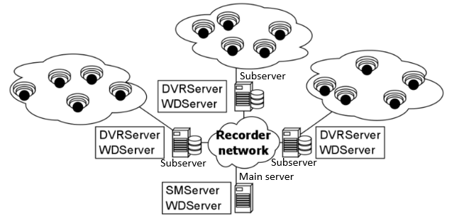
For all camera types, the relative physical placement of the server near the camera significantly impacts bandwidth needs.
A simple scenario, as presented in the below image, has three sites with their own camera network connected to a recording VMS server (subserver).
Each camera has its own bandwidth, and each subserver receives the camera network’s combined bandwidth. The Main Server receives bandwidth from the three subservers.
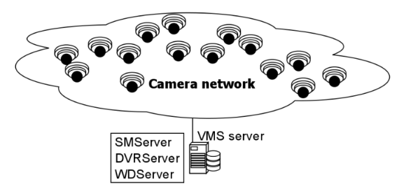
In the below setup, the number of cameras is the same, but they’re connected to only one recording VMS server as a single combined camera network.
The bandwidth received by the sole server is three times greater than what the Main Server would receive from its three subservers.
Any networking approach carries with it its own pros and cons, and these must be weighed and balanced before arriving at a solution.