A counting line is a detection filter optimized for directional object counting (e.g. people or vehicles) in busier detection scenarios.
Examples of such applications may include:
-
People counting with overhead cameras in a retail environment.
-
Vehicle counting with overhead cameras on public highways.
In some scenes, such as entrances with cameras installed overhead, the counting line typically will generate a higher accuracy count than using the aforementioned counters connected to a presence rule.
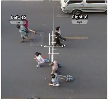
An event is generated every time an object crosses the line in the configured direction.
If multiple objects cross the line together, multiple corresponding events are generated.
These events can be directly used to trigger actions if the Can Trigger Actions property is checked.
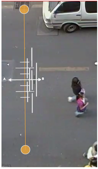
Counting lines are attached to zones configured with a Line shape.
See Zones for more information.
If a counting line is configured with a zone not defined with a Line shape, the zone property will be automatically changed (it will not be possible to change the zone shape back until the counting line stops referencing the zone in question).
Counting lines have a specified direction indicated by the arrow in the UI (direction A or B), the direction of this arrow is governed by the configured zone.
Each instance of the rule counts in a single direction. To count in both directions a second counting line rule must be added to the same zone with the opposite direction selected.
An example rule graph of a two-way counting line configured with a counter is provided to illustrate this below.
NOTE: The maximum number of counting line filters that can be applied per video channel is 5.
Calibrating the Counting Line
In order to generate accurate counts, the counting line requires calibration.
Unlike the object tracking function engine, this cannot be performed at a general level for the whole scene using the 3D Calibration tool.
This is because the counting line is not always placed on the ground plane; it may be placed at any orientation at any location in the scene.
For example, a counting line could be configured vertically with a side-on camera view.
Instead of the 3D calibration tool, the counting line has its own calibration setting.
Two bars equidistant from the center of the line represent the width of the expected object. This allows the counting line to reject noise and also count multiple objects.
To calibrate the counting line:
-
Select the counting line rule.
-
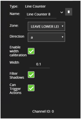
Check the Enable width calibration option.
-
Drag the calibration markers to adjust the distance between the calibration markers until the distance is approximately the size of the objects to be counted. Alternatively, move the Width slider to achieve the same result.
-
The calibration width is displayed within the counting line rule and can be edited directly to change the calibration width.
-
The small markers on either side of the big markers indicate the minimum and maximum width which is counted as a single object.
NOTE: if the Width slider is set to zero then the Enable width calibration checkbox is automatically disabled.
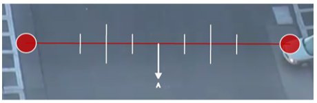
Counting Line Calibration Feedback
To enable the user to more accurately configure the calibration for the counting line, the widths of detected objects are displayed as an overlay next to the counting line when objects pass over it.
By default, this display option is enabled. However, if it does not appear, ensure that the option is enabled on the Burnt-in Annotation settings.
The calibration feedback is rendered as black and white lines on either side of the counting line on the Zones configurations page.Each line represents an object detected by the counting algorithm.The width of the line shows the width of the object detected by the line.The last few detections are displayed for each direction with the latest one appearing closest to the counting line
Shadow Filter
The counting line features a shadow filter which is designed to remove the effects of object shadows affecting the counting algorithm.
Shadows can cause inaccurate counting results by making an object appear larger than its true size or by joining two or more objects together.
If shadows are causing inaccurate counting, the shadow filter should be enabled by selecting the Shadow Filter check box for the line.
It is recommended that the shadow filter only be enabled when shadows are present because the algorithm can mistake certain parts of an object for shadows and this may lead to worse counting results.
This is especially the case for objects that have little contrast compared to the background (e.g. people wearing black coats against a black carpet).
|
Property |
Description |
Default Value |
|
Name |
A user-specified name for this rule |
Line_Counter |
|
Zone |
The zone this rule is associated with |
None |
|
Direction |
Enable counting in the 'A' or 'B' direction (one direction per counting line) |
None |
|
Enable Width Calibration |
Width calibration to allow more accurate counting |
None |
|
Width |
Width calibration value |
0 |
|
Can Trigger Actions |
Specifies whether events generated by this rule trigger actions |
Active |