Local Connections
Today most local network connections are with the use of switches, while hubs were an inexpensive way of connecting devices.
Layer 2 switches offer direct networking with a small number of devices through their MAC addresses. Layer 3 switches are a step up the ladder and offer expanded capabilities.
Routers are also Layer 3 devices, but their use is more relevant on the LAN/WAN border and they function as default gateways for the devices in the local network they’re connected to.
Hubs are an older form of local connection technology and are on the way out.
Hubs do not inspect the packets they receive and broadcast them to all other ports and the devices connected to them.
The use of hubs is discouraged, the use of switches is recommended.
Layer 2 switches can be managed or unmanaged. Unmanaged switches are used to connect a limited number of devices to each other or to a network core.
Managed switches allow users to configure VLANs and set up monitoring and alerts.
Layer 3 switches have the same capabilities and can additionally route IP traffic between VLANs.
Physical local connections over Ethernet wires should not exceed the usual maximum of 100m.
Wireless Connections
The use of wireless cameras or wireless switches, bridges or routers as a part of the VMS or its network is strongly discouraged due to the cameras’ security concerns and uncertain connection reliability of WLAN. All VMS connections should be made with physical cables.
Closed Networks
The most secure way for a surveillance system to be built is to use a dedicated self-contained network that does not have connections to the outside.
The simplest model of this would be to have the system devices connected to an unmanaged Layer 2 switch.
However, being disconnected may not be feasible or desirable in all cases, if e-mail alerts are to be used in the system or if Internet access is required for user activities.
VLANs
VLANs (Virtual LANs) are a method of logically segmenting a local network between different components of the system.
VLANs are configured on switches to segment the device’s ports for enhanced data traffic control. Setting up a VLAN is an alternative to setting up physical segmentation for a network.
It is recommended that you consult an ICT expert or your IT department before planning and configuring VLANs on your VMS network’s networking devices.
Layer 2 switches forward data based on device MAC addresses, and any VLANs configured on the switch would shunt data from certain ports to named trunk ports.
This can be used in isolating the camera network to communicate with only a VMS server’s network card.
Any VLANs configured on a Layer 2 switch cannot communicate between each other without the device being connected to a Layer 3 network device and the VLANs trunked to it through the interface connecting it.
Layer 3 switches with IP routing can support multiple VLANs that can communicate between each other, as data is routed based on target IP addresses.
Each VLAN could also be in charge of its own subnet, and IP addresses need to be assigned for them.
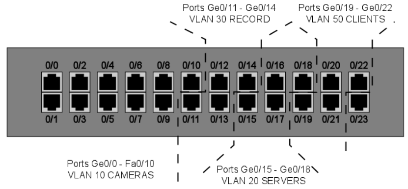
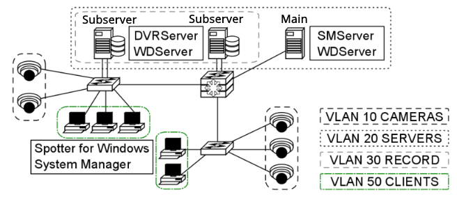
One example of a VLAN setup in the VMS would have (if all system devices are ultimately connected to the same Layer 3 switch) a VLAN for the camera network, a VLAN for the recorder network’s camera network NICs, a VLAN for the recorder network’s server-server/server-client network NICs along with the SMServer’s NIC and a VLAN for local computers running Spotter for Windows and System Manager.
Ports should be reserved for these purposes as needed. Layer 2 switches can be used to allow more devices to be connected to the network, as long as these are connected to the VLAN-configured ports.
VLANs can be used across multiple switches. Having multiple VLANs in the network will necessitate having routing capabilities in the network in order to route IP packets between the VLANs.
This can be done with a Layer 3 switch, a router or with router-on-a-stick, where you have a routing device with a single LAN connection to the Layer 2 switch.
The device routes between the VLANs, allowing traffic between them.
With VLAN segregation, the exact physical location of each system device is largely irrelevant to the network. To the network, VLANs are their own local networks that the router routes traffic between.
With multiple VLANs, each device needs to have an IP address configured, so the Layer 3 device can route the traffic between them.
Inter-VLAN routing requires configuring the Layer 3 switch and enabling routing on it. Specific actions and commands are dependent on the manufacturer of the device, but usually, the procedure is as follows:
-
Enable IP routing
-
Assign addresses to the VLANs (e.g. VLAN 10 would have 192.168.10.1/24)
-
These will be the default gateways for the end devices in the VLANs
-
-
Configure a default route for the switch
QoS
Quality of Service is a set of strategies usually standardized with network device manufacturers.
QoS is used to ensure a certain standard of quality in the transmissions configured on a managed device that is serving as a part of a shared network.
When QoS is configured on VLANs, it prioritizes their bandwidth so it is not as readily consumed by other traffic and that the information going through switches does not degrade.
While QoS can be used with any application connection or by users, using it with VLANs is easier to manage and configure.
QoS is generally not needed on dedicated networks, as there’s no need to prioritize the traffic the network is dedicated to transmitting.
In larger, shared networks, however, it becomes vital in preventing performance fluctuations.
Virtual Private Network (VPN)
VPN (Virtual Private Network) can be used to establish secure connections between two or more LANs or to have a well-protected point-to-point connection over the Internet.
VPN uses encryption and authentication protocols preventing unknown computers from accessing data delivered between two or more local network sites.
VPN tunnels for LAN-to-LAN connections can be created using hardware-to-hardware connections, usually with routers that can be used as firewalls or dedicated VPN devices.
VPN tunnels for point-to-point connections are typically created with the combination of a hardware firewall functioning as a VPN server and software VPN client connections.
After VPN is configured, Mirasys VMS can be installed and used as if it were in a closed network.
Do note that the use of a VPN connection might reduce available bandwidth and consume other resources used by the VMS, which may have a negative impact on the performance of the system or its network.
A data packet can have an MTU (Maximal Transmission Unit) size of 1500 bytes (12 kilobits) before it’s fragmented by a Layer 3 device for delivery over IP networks.
VPN adds additional information to the packet header, so the packet is fragmented.
This fragmentation could lead to packets arriving in the wrong order and not playing the video properly on some end applications.
It is recommended to set the cameras in the system to have their TCP and UDP MTUs set to 1300 bytes.
VPN Methods
VPNs can be set up with a certain variety of methods afforded by the ICT networking industry.
Routers can be set up to create Layer 3 VPN tunnels between them, connecting large sites to each other, a site can have dedicated hardware for VPNs or a server can be configured through software settings to manage VPN tunnels.
It is recommended to consult an ICT expert or your IT department for in-depth details on how to set up VPNs and what type of solution is best.
Layer 2 Tunneling Protocol
L2TP (Layer 2 Tunneling Protocol) is a tunnelling protocol used to support VPNs.
The protocol itself doesn’t provide any encryption or data confidentiality but relies on an encryption protocol that it passes within the tunnel to provide privacy.
IPSec is often used to secure L2TP packets by providing confidentiality, authentication and integrity.
The combination is generally known as L2TP/IPSec.
When a VPN connection has been established in an L2TP/IPSec VPN tunnel, L2TP packets are encapsulated by IPSec, so no data about the private network can be ascertained from the secured packets.
Also, it is not necessary to open UDP port 1701 on firewalls between the tunnel endpoints, since the secured packets are not acted upon until after IPSec data has been decrypted and stripped at the endpoints.
L2TP allows the creation of a VPDN (Virtual Private Dialup Network) to connect remote clients to their corporate network by using a shared infrastructure, such as the Internet or the ISP WAN.
Desktops and laptops using Microsoft Windows Vista and later operating systems can form remote L2TP VPN connections with a private network.
A short setup guide example is presented in chapter 4.6.3.
Layer 3 VPNs
VPN tunnelling between Layer 3 devices is used to connect LANs with each other. This is commonly done between routers connected to a WAN such as the Internet.
Routers and routing hardware firewalls (e.g. Cisco ASA or SonicWall devices) can maintain IPSec VPNs between each other over the Internet.
VPN concentrators
VPN concentrators are networking devices specialized in providing secure VPN connections and message delivery between VPN nodes.
Its capabilities are realized by adding data and network security to communications that it routes. It is meant to create and manage a large number of individual VPN tunnels.
A VPN concentrator is typically used for creating site-to-site VPN connections. Their tasks include:
-
Establishing and configuring VPN tunnels
-
Authentication of users
-
Assigning tunnel/IP addresses to users
-
Encryption and decryption of data
-
Insurance of end-to-end data delivery
VPN Servers
VPN servers come in two general types: hardware servers and software-based servers.
Hardware VPNs are purpose-built networking devices that connect to an Internet connection from within a service site and provide improved VPN capabilities when compared to application-based servers.
Usually, these devices can support multiple simultaneous connections. Servers are normally managed through web browsers contacting their IP addresses.
Software-based VPN servers can be made from stripped-down or bare-bones desktop computers with the appropriate VPN software application or server operating system installed and network connections configured. There are numerous applications available through a myriad of providers that can form a stand-alone VPN server on a desktop/server operating system environment.
Some server operating systems come with built-in capabilities to function as VPN servers. The number of supported connections depends on the running server software and the number of ports on the computer’s NICs.
NOTE: some VPN server applications may be incompatible with other VPN standards.
Configuring A VPN
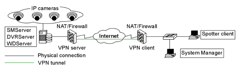
When the Mirasys VMS system is used with VPN, tunnels are created between the system’s servers with DVRServer, SMServer, and client applications.
An easy way to use VPN is to create a network-to-network connection between sites.
The recording servers should be on the VPN server’s network, and the clients on the VPN client’s network, as DVRServer, does not automatically send data to the applications.
All data connections are initiated by the client applications.
The following points are quick guidelines on how to use VPN with the VMS. To have more comprehensive instructions, it is advised to consult an ICT expert and VPN software/hardware documentation.
To use VPN:
-
Create a VPN tunnel for the local network where the Mirasys VMS system is located. This is configured on a VPN server.
-
Create a similar tunnel on the client site-local network (Spotter for Windows/System Manager).
-
Select a VPN model that allows for a continuous connection.
-
Test the connection. Once connections are viable, start configuring the Mirasys VMS system.
Example Of Setting Up A VPN Remote Connection
Devices using Microsoft Windows can form L2TP VPN connections to private networks without the express need of a separate gateway.
The remote user contacts the Layer 3 device on the private network to establish a secure line of communication over a WAN, such as the Internet.
A Windows 7 user would go through the following steps to establish a VPN connection between their computer and a Layer 3 device:
-
Open the Start Menu and type “VPN” in the search box
-
Click the “Set up a virtual private network (VPN) connection” icon to open the VPN creation window
-
Enter the server information
-
Type the VPN server hostname in the “Internet address” field
-
Type the name of your VPN destination in the “Destination Name” field
-
Check the “Don’t connect now; just set it up so I can connect later” box
-
Click “Next”
-
-
Enter your VPN account username and password in the appropriate fields and click “Create”
-
Open the Network and Sharing Center from the Start Menu by searching Network in the search box
-
Click “Connect to a network,” a list of VPNs pops up.
-
Right-click on the VPN connection you just created and choose “Properties”
-
Click on the “Type of VPN” pop up menu and select “L2TP/IPSec”
-
Click on the “Advanced Settings” button.
-
-
In the “IPSec Settings” dialogue, click the radio button labelled “Use preshared key for authentication”
-
Enter the key to the VPN into the textbox labelled “Key”
-
Click the “OK”
-
-
In the VPN connection properties, open the “Networking” tab
-
Make sure the “Internet Protocol Version 4(TCP/IPv4)” and “Client for Microsoft Networks” items are checked
-
If other protocols are checked, uncheck them by clicking on the checkbox.
-
-
Click “OK” to finish, then connect to the VPN server by this connection
DynDNS
Dynamic DNS (Domain Name System) services resolve IP addresses to simpler hostnames, e.g. recorder.DynDNS.xx instead of 127.0.0.1.
The DynDNS service updates the IP addresses corresponding to each hostname periodically or in some cases automatically detects changes and updates immediately.
DynDNS is most commonly used with recording servers and cameras. Many manufacturers host their own private DynDNS services free to users who purchase their equipment.
Domain
Building a Mirasys VMS system in a domain does not significantly differ from working with other networks. In a domain, only administrative users can install the server software and the client applications.
User rights policies can be used to restrict or permit user access to the client applications.
In a domain, all computers are named, and the VMS servers can be named according to the domain infrastructure.
Static IP Addresses are to be used with the devices running DVRServer and the SMServer.
SQL Databases
SQL databases refer to shared relational databases in a local network that uses the SQL (Structured Query Language) programming language.
In larger setups of the VMS, the SQL database is handled by the SMServer and client applications receive information from it whether or not there’s a database in use.
In smaller VMS environments, VMS servers running DVRServer are responsible for alarm event data storage.
SQL databases are used in the system to store:
-
DVRServer metadata
-
Watchdog events on the SMServer
-
With the XMC (eXtended Monitoring Center) license
-
Audit trails
-
The recording servers’ alarm events
-
Alarm configurations
-
Alarm occurrences
-
Alarm edits/changes
Virtual Machine Network Traffic Routing
Virtual machines can have two IP addresses simulating two NICs: “inside” (host-only) IP addresses and “outside” addresses that are seen by the local network.
The purpose of a virtual machine host is to essentially simulate a network segment and device collection.
Machines on the same VLAN on the same switch can communicate with each other.
Machines on different VLANs on the same switch cannot communicate unless the traffic passes through a Layer 3 device (router or Layer 3 switch).
Note: some virtual machine mediums have a cap on the number of virtual machines that can be configured for a single host.
VMs on the same VLAN on the same host.
Virtual machines can be in the same VLAN connected to the same virtual switch within the VM host’s internal (virtual) network.
All communication between the virtual machines is done internally and the host’s physical NIC is not involved.
VMs on different VLANs on the same host
Virtual machines in separate VLANs communicate in the same manner as any VLAN-connected device would: traffic between VLANs is routed by a Layer 3 device.
Traffic is sent through the host’s NIC to the Layer 3 device and is sent back to the other VLAN within the host.
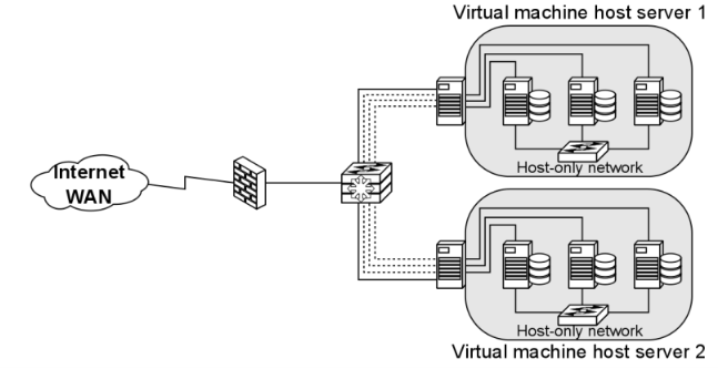
VMs on different Switches on the same host
If a VM host is configured to have two or more virtual switches in its system, the virtual machines need to send their traffic to an outside networking device to reach the other virtual switches.
The device can be Layer 2 or Layer 3.
VMs on different hosts on the same VLAN.
Virtual machines on the same VLAN communicate exactly like physical devices on the same VLAN would.
Intra-VLAN communication is a Layer 2 process, so communication between them is trafficked through their physical hosts’ NICs and a switch.
The physical hosts must have a distributed virtual switch, however.
Universal Plug And Play
Universal Plug and Play are meant to automate device discovery and configuration on a local network, aiming to eliminate manual port forwarding and create an automatic port mapping.
However, UPnP is often unreliable in practice. The technology is meant for consumer/home networking and is usually unsuitable for business network use.
The function is usually disabled on networking devices and port forwarding is manually configured.
As far as maintenance and troubleshooting are concerned, UPnP rarely provides error information in the event of a port mapping failure.
Time Protocols
Time protocols are used to sync device times with the rest of the world. In video surveillance, this is paramount to the entire purpose of the service.
When setting up the VMS, every managed device should have its time synced to provide maximum reliability on the reported time of the video feeds.
There are three-time protocols used for time syncing:
-
NTP (Network Time Protocol), is intended to synchronize all participating computers within a few milliseconds of UTC (Coordinated Universal Time).
-
The protocol does not transmit time zone or daylight savings time information, so these need to be configured on devices manually.
-
-
SNTP (Simple Network Time Protocol), is the most commonly used time protocol in the IT/ICT industry and, as the name implies, a simplified version of NTP, being only up to a millisecond less accurate.
-
Windows Time, a Microsoft proprietary time protocol used in Microsoft Networks.
-
Use is not recommended, as configuring and managing this requires changes in the Windows registry and accuracy cannot be guaranteed.
-
A time server running one of these protocols provides time to networked devices on request.
Synchronization is most often performed every hour, though users can choose to have syncing occur more often, in cases where high accuracy is required.
Surveillance devices often state 'time synchronization' instead of SNTP or NTP specifically. It is recommended to have all devices in the system network receive time synchronization from the same source.
There are three basic ways to serve time to a network:
-
Public Servers on the internet, such as time.gov and ntp.org. Accessing these sources requires an Internet connection.
-
Private Servers can receive time from public servers and function as the local network’s time servers. These must be configured with third-party programs on any computer or server on the network.
-
GPS Servers are a solution for closed surveillance networks. These devices receive GPS data from the system’s satellites via an antenna.
Multi-Channel Devices
Some camera models may be equipped to send their video feeds as separate channels, with each channel capable of carrying a number of video streams.
These cameras are treated by the system as being separate video devices sharing a common IP address.
As each channel is treated as a separate camera, these extra channels take up a place in the system’s license.
Multicasting
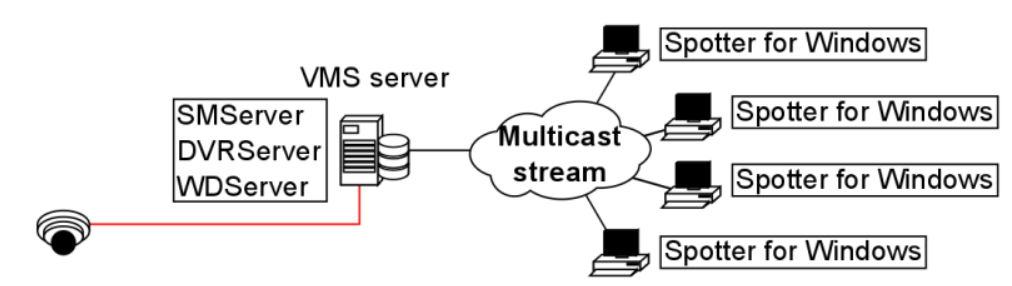
When a unique Spotter stream is opened multiple times, the recording VMS server and the network connected to it face unnecessary strain as each stream is treated as a separate entity.
Multicasting enables a single stream to be opened and sent to multiple spotter clients simultaneously.
When using multicast, only a single instance of each video channel is sent to the local network.
All applications in the local network can receive the single stream, so network bandwidth usage is much lower than when sending streams for each streaming application separately.
The feature needs to be configured in the System Manager application.
As some network hardware may be incompatible with multicasting, the compatibility of all network components (such as routers and switches) should be checked before configuring multicasting.
A multicast network must meet the following requirements:
-
Routers must support multicast
-
Routers that connect multiple networks must support PIM (Protocol Independent Multicast)
-
Ethernet switches must support IGMPv2 (Internet Group Multicast Protocol version 2) snooping
-
Most out-of-the-box Ethernet switches are not configured to properly support Multicast
-
An IGMP querier is required in each VLAN
-
IGMP Query is normally supported by routers and high-end Layer 3 switches
-
One querier per VLAN is needed
Multistreaming
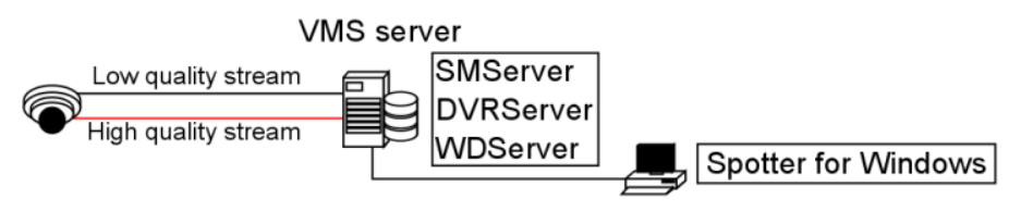
Multistreaming enables separate video feeds from a single camera.
The feature allows for separate streams to be used for recording and viewing, as well as an additional stream for remote streaming.
Support for this feature is dependent on the specific camera model.
Please refer to the camera manufacturer documentation and the supported cameras list to see what cameras support the feature.
It should be noted that the extra stream causes additional network load.
Bandwidth factors are further elaborated in chapter 5.
The feature needs to be configured in the System Manager application.
Remote Workstation
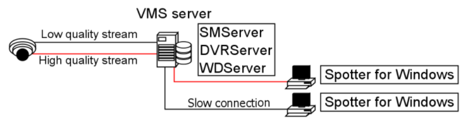
In some cases, it is necessary to open the same video stream in different locations with different image quality.
For example, a separate image quality might be required for the security centre and a separate one for off-site use with slow network connections.
The remote workstation functionality enables users to open an additional video stream with different image quality in comparison to the “prime” viewing stream.
The feature is currently supported by specific camera drivers.
Please refer to the Mirasys VMS supported IP cameras guide and the camera manufacturer documentation to see what cameras support the feature.
It should be noted that the extra stream causes additional network load. Bandwidth factors are further elaborated in chapter 5.
The feature needs to be configured in System Manager, and in the Spotter / GatewayServer XML settings for the computer in which the remote workstation stream is used.
Remote Access
Check more information under Frequently Asked Questions and Spotter Tips and Tricks.
Edge Storage
The Edge Storage functionality enables uninterrupted recording during network disconnects between the camera and the DVRServer.
During connection failures, the recorded footage is saved on the camera’s local data storage, e.g. an SD-card.
Once the network connection has been re-established, the saved video is transmitted from the camera’s local storage to the DVRServer.
Support for this feature is dependent on specific camera models.
Please refer to the camera manufacturer documentation and the supported cameras list to see which camera models can support the feature.
This feature is configured solely through the camera’s own configuration utility, and it doesn’t require any modifications in the System Manager application.
Please refer to the camera’s documentation for instructions on enabling Edge storage.