The best way to solve problems is to prevent them before they happen.
With best practices in general network implementation, users can save a lot of time, effort and resources when they put in a few extra hours at the planning and implantation phase of setting up networks.
Basic rules: Document changes, document addition, document removal, document everything you do or change in the system.
If a change causes problems later on with the system due to unforeseen consequences, documentation will help solve said problems.
Network Topologies
As the first step with system networking, plan out the physical network and maintain current topologies for record-keeping.
Anything well planned is already halfway done. A clear network topology is useful in narrowing down network bottlenecks, failure points and sections that could be improved or expanded.
A network topology should map the whole network the system would encompass.
This includes the cameras, recording devices running DVRServer and other servers, decoders, connection types, network switches and any workstations with Spotter for Windows and System Administrator applications installed and connected to the network.
Also, if the VMS network is connected to the Internet, firewalls or gateway servers should be included in the topology.
Networks the devices have been assigned to should also be marked, as well as device IPs on the relevant connections.
Switches and routers should have their interfaces marked as well, either on the topology itself or on a list close to the devices. If VLANs have been assigned, these need to be marked as well.
The software contained within the end devices do not need to be marked, but these should be recorded in the documentation as well.
An example topology below has the VMS network connected to the internet through a firewall running NAT.
The clients and the hybrid recording VMS server (running SMServer) are connected to the firewall through a Layer 3 switch, so the connections within the network can be segmented into their own subnets.
The camera network is connected to the DVRServer through an unmanaged Layer 2 switch, so their packets are switched by MAC addresses alone.
Segments of the VMS are placed under their own subnets for easier navigation and possible expansion, e.g. with more users or more servers.
These subnets can be placed under VLANs in the Layer 3 switch’s configuration.
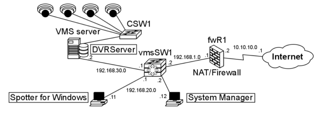
The interfaces of the switches are marked and labelled.
The unmanaged Layer 2 switch’s IP addresses don’t need to be configured for this particular setup.
|
Hostname |
Interface |
Interface label |
|
CSW1 |
Ge0/0 |
SWITCH-RECORDER |
|
Ge0/1 |
CAMERA1 |
|
|
Ge0/2 |
CAMERA2 |
|
|
Ge0/3 |
CAMERA3 |
|
|
Ge0/4 |
CAMERA4 |
|
Hostname |
Interface |
IP address |
Subnet mask |
Interface name |
|
vmsSW1 |
Ge0/0 |
192.168.1.2 |
/28 |
vmsSW1-fwR1 |
|
Ge0/1 |
192.168.30.1 |
/24 |
vmsSW1-Recorder |
|
|
Ge0/15-24 |
192.168.20.1-10 |
/24 |
vmsSW1-client |
If you are unsure as to how to keep up topology illustrations and related device and network documentation, it is recommended to consult your IT department or an ICT expert.
Physical Setup
Along with a clear topology, planning the routes of physical connections through a building or site can save a lot of heartache and time.
Mapping the devices and cabling in a site, even if it’s a three-room section of a floor, can help in selecting the cabling that will be used as well as the placements of the devices.
With cabling, the appropriate length cabling should be used to reduce the chance of interference or overheating coming from coiled cables or straining them when they’re just that inch too short for the required distance. Distances between the ports on networked devices need to be pre-planned or measured to make sure the correct cable will be gotten for it.
Cable labelling can be done with taped labels or with cable colours.
Colours will help in grouping the cables to the connection groups they’re a part of.
Cables should also be bunched or guided to make sure they do not get tangled. Using cable trays can keep them out of the way and prevent any tripping or snagging hazards.
The actual cables themselves should be planned by the estimated amount of interference they might face on their routes.
Electromagnetic interference affecting cables can lead to image quality deterioration or even complete image loss.
Standard cables are UTP (Unshielded Twisted Pair) cables. When interference is expected or encountered, STP (Shielded Twisted Pair) cables should be used.
Elements that cause EMI:
-
High Voltage Wiring: Power wiring can interfere with data transmission even when run parallel to each other. Even wiring running a compliant distance apart within a grounded raceway can be a source of video interference. The best practice is that any data cabling sharing the same raceway with power cables, regardless of how either is contained, must be run using an STP cable.
-
Inductive Sources: Data cabling run near common electromechanical components like electric motors, power transformers, magnetic coils, or solenoids can introduce significant EMI.
-
Radio sources: Common low powered communication radios disrupt data transmission. High-powered repeaters or transmitters necessitate using STP to eliminate problems.
-
Fluorescent Lights: Fluorescent lights are common to light fixtures and can cause interference to cable bundles in overhead cable runs. Cable trays or STP cables should then be used.
Cybersecurity
In the field of networked security surveillance, cybersecurity is paramount.
To be secure in your network, you must be educated in it. It is advisable to read all the relevant materials for each component that is to be used in or with the VMS.
Cybersecurity is considered to be a layered defence against threats that would compromise sensitive systems or data.
Protection can be visualized as an onion or concentric walls, with physical access to the system as the outer layer and the protected service or data at the centre.
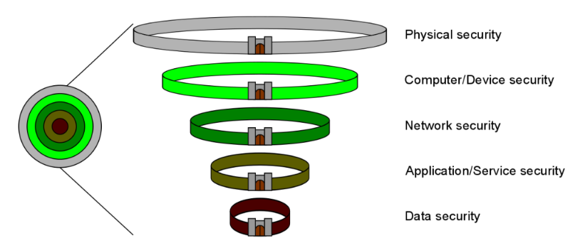
Security for the layers generally follows the following scheme:
-
Physical access to the system’s network components and devices is restricted and the devices are secured in cabinets in safe locations
-
Computers and other devices accessing the system require authorized login credentials to open and when opened, they’re secured by virus protection software
This protects against intrusions from inside the physical location of the system or its components
-
The network is secured against snooping, hijacking, DoS attacks and unauthorized outside access by firewalls, private networks or isolation
This protects against data intrusions from outside the physical location of the system or its components
-
System applications on computers and services on servers require authorized logins and a connection to the system for verification
-
The recorded data is secured with encryption and is only accessible to the appropriate applications used by authorized users
Each layer is to be maintained to minimize the chance of recorded data or system information ending up in unwanted hands.
Remember, security begins with you.
User Privileges
Only allow essential users to have elevated or admin privileges on any of the devices, services or system applications.
Grant access only to users you trust and the more privileges a user is supposed to have, the more trustworthy they need to be. A user should always need to check their privileges.
Virus Protection
If you maintain internet connections from within the VMS network, keep all virus security programs and firewalls up to date and functioning.
Consult the documentation for the programs you have in use.
Even in closed networks, you should check the systems for malware from time to time, because there are still possibilities for your devices to get infected, for example by downloading a file from a USB stick to a PC in the closed network.
Also, remember to open needed ports from the firewall to enable Mirasys VMS systems to work properly. too strict firewall protection is the number one cause for problems in the VMS networks.
Passwords
One of the key aspects of cybersecurity beyond installing physical security devices, such as firewalls, is to configure all needed devices and to use non-default passwords.
Default logins and passwords are always the first to be tried in an attack.
Always input new passwords to cameras and other devices. Change your devices’ passwords regularly.
Another important part when it comes to passwords is to have them secured when transmitted over a network.
Password transmissions between VMS clients and servers are secured with public key encryptions.
However, if you do not use a password at all, attackers snooping on the network connection are able to see this.
When a user logs in, there’s a login request via a TCP packet from the client to the server.
The part of the query for login that is relevant to this consideration has a string format of [...]userName.password.networkAddress[...] (password as seen by the WireShark network traffic capture tool in bold).
When transmitting the query, the Spotter client encrypts it.
[output omitted]
Admin....@NpxrzbgeIAjA5oaQ4LvF0GGe4seCc9n37apH5goN/buAtucUbY/zwIYWByJEAlqQ......10.10.11.165
[output omitted]
If you use a blank password (as in no password at all), the same query is seen without a password, tipping anyone snooping off to the fact that the system may be unsecured.
And if the server responds with an OK, the system really is unsecured.
[output omitted]
Admin...........10.10.11.165
[output omitted]
To counter this, use a password. Any password is better than none, and a strong password is better than a simple one.
Password Strength
A strong password is at least 8-10 (recommended 12-14+) characters long, has both cases in use and has special characters and numbers in it.
Even if your password is strong, it’s best practice to change it regularly.
It’s best practice to avoid words and phrases that are easily guessed (such as password12345), as crackers can test dictionary words in passwords along with brute force cracking that tries each possible character combination one by one.
Computers can also harness graphics cards (GPUs, Graphics Processor Units) to number-crunch the passwords and try each one.
As an example, a Radeon HD5770 graphics card (released for the market in 2009) can perform 3.3 billion guesses per second.
Moore’s law dictates that computing power doubles every two years.
With multiple GPUs per computer, newer GPUs becoming available, distributed computing and botnets, computer systems with unrestricted login tries could face significant attempts at breaking through.
If your password is to be made of a phrase or certain words, they should be as obscure as you can think of, and they need to be turned into a form that is as complex as it can be through character substitution and spelling corruption.
User-defined passwords made primarily through word generation can be strengthened through character swapping.
Character substitution is a simple way of increasing password complexity.
Randomly generated passwords also use the same character ranges.
This increase is presented in the below table, where an eight-digit password is made increasingly complex: first with a case-insensitive string of letters, then with some letters made upper/lower case, then substituting characters with numbers, then with special characters.
|
Character type |
Possible characters |
Possible combinations |
Crack time |
|
Upper/lower case |
26 |
2.09x10¹¹ |
2s |
|
Mixed case |
52 |
5.30x10¹³ |
8min, the 50s |
|
+Numbers |
62 |
1.60x10¹⁴ |
26min, 37s |
|
+Special characters |
95 |
3.03x10¹⁵ |
8h, 24min, the 20s |
Making a password nine characters long would extend PC brute force cracking time to 39 days.
As an example, “Taek_Mi_2_da_Rivah” is a password that is complex, yet can be easy to remember.
The words are corrupted to a degree that they can’t fall to dictionary attacks and its brute force strength is brought by the fact that it is an 18-character password with numbers, upper and lower case letters and special characters, giving 3.41x1035 possible combinations.
This would yield a PC cracking time of 108 quadrillion years. Even the Tianhe-2, the world’s fastest supercomputer at this time, running 33.86x10¹⁵ operations per second would take 319 billion years to break that password with brute force.
Add any character to the back of the password and it’ll take 32 trillion years for Tianhe-2 to break it with brute force. Cracking a well-constructed password can be an astronomical task indeed.
Network Segmentation And Device Segregation
As mentioned in chapter 2.1, it’s best practice to keep the camera and server networks on separate network segments, so there’d be less chance for camera signals to face interference from other traffic in the system and to improve system security as a safeguard against unwanted connections.
This should be done with closed networks connected directly to recording VMS servers, or by setting up VLANs in the network devices.
Consult an ICT expert on how to best implement network segmentation and device segregation.