Camera calibration is required in order for VCAcore to classify objects into different object classes.
Once a channel has been calibrated, VCA Core can infer real-world object properties such as speed, height and area and classify objects accordingly.
Calibration is not needed to do when using Deep Learning tracking, only when using normal VCA or Deep Learning Filter.
Camera calibration is split into the following sub-topics:
-
Enabling Calibration
-
Calibration Controls
-
Calibrating a Channel
-
Advanced Calibration Parameters
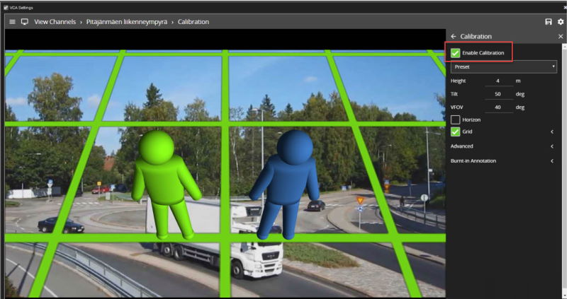
Enabling Calibration
By default calibration is disabled.
To enable calibration on a channel, check the Enable Calibration checkbox.
Calibration Controls
3D Graphics Overlay
During the calibration process, the features in the video image need to be matched with a 3D graphics overlay.
The 3D graphics overlay consists of a green grid that represents the ground plane.
Placed on the ground plane are a number of 3D mimics (people-shaped figures) that represent the dimensions of a person with the current calibration parameters.
The calibration mimics are used for verifying the size of a person in the scene and are 1.8 metres tall.
The mimics can be moved around the scene to line up with people (or objects which are of a known, comparable height) to a person.
Mouse Controls
The calibration parameters can be adjusted with the mouse as follows:
-
Click and drag the ground plane to change the camera tilt angle.
-
Use the mouse wheel to adjust the camera height. - Drag the slider to change the vertical field of view.
Note: The sliders in the control panel can also be used to adjust the camera tilt angle and height.
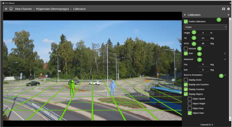
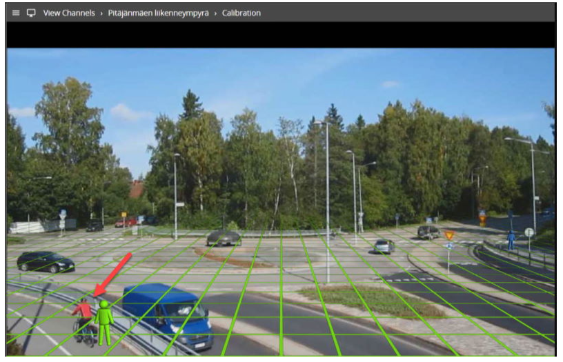
Control Panel Items
The control panel (shown on the right-hand side in the image above) contains the following controls:
-
Height: Adjusts the height of the camera
-
Tilt: Adjusts the tilt angle of the camera
-
VFOV: Adjusts the vertical field of view of the camera. Note: A correct value for the vertical camera field of view is essential for accurate calibration and classification.
-
Horizon: Enables/disables the horizon display. Useful to line up against a horizon in a deep scene.
-
Grid: Enables/disables the ground plane grid display. The expand/collapse control (<) exposes additional settings to vary the colour, opacity and size of the ground plane grid.
-
Advanced: Exposes advanced settings for controlling the pan and roll of the camera.
-
Burnt-in Annotation: Exposes the Burnt-in Annotation controls for convenience.
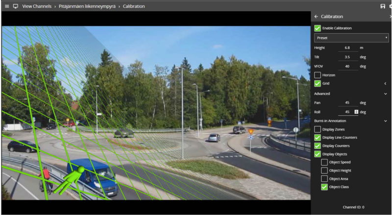
Context Menu Items
Right-clicking the mouse (or tap-and-hold on a tablet) on the grid displays the context menu:
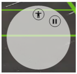
Performing the same action on a mimic display the mimic context menu:
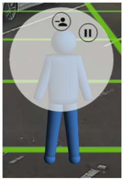
The possible actions from the context menu are:
Calibrating a Channel
Calibrating a channel is necessary in order to estimate object parameters such as height, area, speed and classification.
If the height, tilt angle and vertical field of view corresponding to the installation are known, these can simply be entered as parameters in the appropriate fields in the control panel.
If however, these parameters are not explicitly known this section provides a step-by-step guide to calibrating a channel.
Step 1: Find People in the Scene
Find some people or some people-sized objects in the scene.
Try to find a person near the camera, and a person further away from the camera.
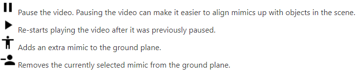
It is useful to use the play/pause control to pause the video so that the mimics can be accurately placed. Place the mimics on top of or near the people:
Step 2: Enter the Camera Vertical Field of View
Determining the correct vertical field of view is important for accurate calibration.
The following table shows pre-calculated values for the vertical field of view for different sensor sizes.
|
|
Focal Length(mm) |
1 |
2 |
3 |
4 |
5 |
6 |
7 |
8 |
9 |
10 |
15 |
20 |
30 |
40 |
50 |
|
CCD Size (in) |
CCD Height(mm) |
|
|
|
|
|
|
|
|
|
|
|
|
|
|
|
|
1/6" |
1.73 |
82 |
47 |
32 |
24 |
20 |
16 |
14 |
12 |
11 |
10 |
7 |
|
|
|
|
|
1/4" |
2.40 |
100 |
62 |
44 |
33 |
27 |
23 |
19 |
17 |
15 |
14 |
9 |
7 |
|
|
|
|
1/3.6" |
3.00 |
113 |
74 |
53 |
41 |
33 |
28 |
24 |
21 |
19 |
12 |
11 |
9 |
6 |
|
|
|
1/3.2" |
3.42 |
119 |
81 |
59 |
46 |
38 |
32 |
27 |
24 |
21 |
16 |
13 |
10 |
7 |
|
|
|
1/3" |
3.60 |
122 |
84 |
62 |
48 |
40 |
33 |
29 |
25 |
23 |
20 |
14 |
10 |
7 |
5 |
|
|
1/2.7" |
3.96 |
126 |
89 |
67 |
53 |
43 |
37 |
32 |
28 |
25 |
22 |
15 |
11 |
8 |
6 |
|
|
1/2" |
4.80 |
135 |
100 |
77 |
62 |
51 |
44 |
38 |
33 |
30 |
27 |
18 |
14 |
9 |
7 |
5 |
|
1/1.8" |
5.32 |
139 |
106 |
83 |
67 |
56 |
48 |
42 |
37 |
33 |
30 |
20 |
15 |
10 |
8 |
6 |
|
2/3" |
6.60 |
|
118 |
95 |
79 |
67 |
58 |
50 |
45 |
40 |
37 |
25 |
19 |
13 |
9 |
8 |
|
1" |
9.60 |
|
135 |
116 |
100 |
88 |
77 |
69 |
62 |
56 |
51 |
35 |
27 |
18 |
14 |
11 |
|
4/3" |
13.50 |
|
|
132 |
119 |
107 |
97 |
88 |
80 |
74 |
68 |
48 |
37 |
25 |
19 |
15 |
If the table does not contain the relevant parameters, the vertical FOV can be estimated by viewing the extremes of the image at the top and bottom.
Note that without the correct vertical FOV, it may not be possible to get the mimics to match people at different positions in the scene.
Step 3: Enter the Camera Height
If the camera height is known, type it indirectly. If the height is not known, estimate it as far as possible and type it indirectly.
Step 4: Adjust the Tilt Angle and Camera Height
Adjust the camera tilt angle (and height if necessary) until both mimics are approximately the same size as a real person at that position in the scene.
Click and drag the ground plane to change the tilt angle and use the mouse wheel or control panel to adjust the camera height.
The objective is to ensure that mimics placed at various locations on the grid line up with people or people-sized- objects in the scene.
Once the parameters have been adjusted, the object annotation will reflect the changes and classify the objects accordingly.
Step 5: Verify the Setup
-
Once the scene is calibrated, drag or add mimics to different locations in the scene and verify they appear at the same size/height as a real person would.
-
Validate that the height and area reported by the VCAcore annotation look approximately correct.
-
Note that the burnt-in -annotation settings in the control panel can be used to enable and disable the different types of annotation.
-
Repeat step 4 until the calibration is acceptable.
Advanced Calibration Parameters
The advanced calibration parameters allow the ground plane to be panned and rolled without affecting the camera calibration parameters.
This can be useful to visualize the calibration setup if the scene has a pan or roll with respect to the camera.
Note: the pan and roll advanced parameters only affect the orientation of the 3D ground plane so that it can be more conveniently aligned with the video scene, and does not actually affect the calibration parameters.